


 English
 русский
 Español
 عربى
عربى
Author: Admin Date: 2026-09-18
How Can Brake Motor Control Be Coordinated With PLC and VFD Systems?
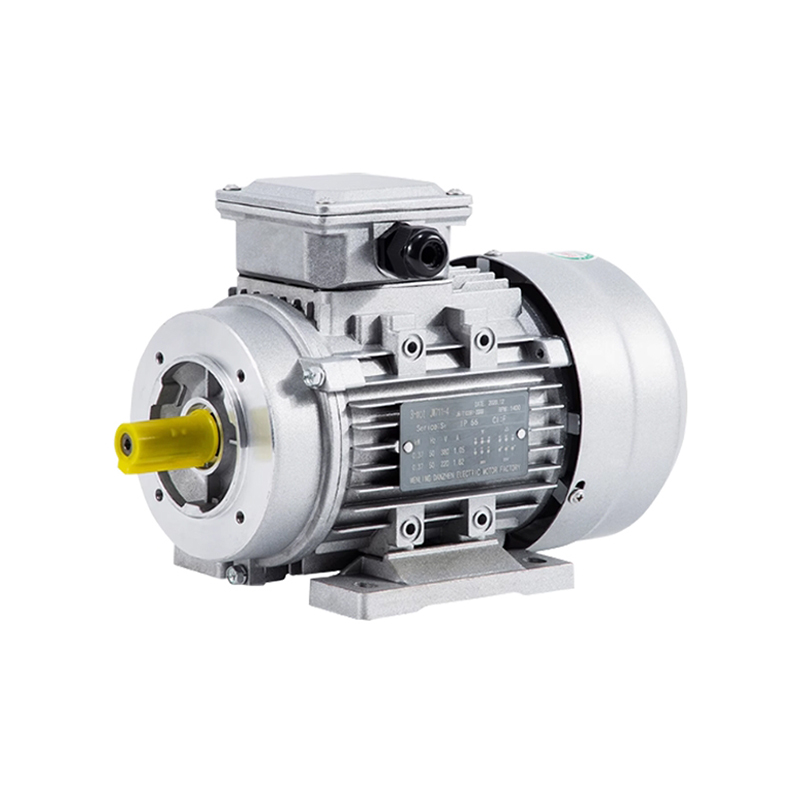
As automated machinery becomes more dependent on coordinated motion, the relationship between the motor, brake, VFD, and PLC has become an important engineering consideration. A braking system may operate correctly on its own, yet still cause positioning errors or unnecessary mechanical stress if its release and engagement sequence does not match the drive system. For conveyors, packaging machines, lifting equipment, and automated handling systems, a properly integrated Brake Motor can help coordinate acceleration, deceleration, stopping, and load holding as part of the complete motion-control process.
Why Brake Timing Matters
A brake motor does not simply switch between running and stopped conditions. In many automated systems, the brake needs to release before the motor develops significant torque and engage only after the motor has sufficiently decelerated.
If these actions occur at the wrong time, several problems may appear:
- The motor may start against an engaged brake.
- The machine may move before the brake is fully released.
- The brake may engage while the shaft is still rotating rapidly.
- The final stopping position may become inconsistent.
These issues are particularly relevant to indexing conveyors and automated production equipment, where repeatable motion is part of the machine sequence.
Coordinating the Brake With a VFD
When a variable frequency drive controls the motor, the brake normally needs to be considered separately from the VFD's speed-control function. The VFD manages motor acceleration and deceleration, while the mechanical brake provides stopping or holding when required.
A practical control sequence may follow this logic:
- Start: brake releases, the motor receives the drive command, and acceleration begins.
- Run: the motor operates under the required speed or torque control.
- Stop: the VFD commands deceleration, the motor approaches the required stopping condition, and the brake engages.
The exact sequence depends on the equipment, brake design, drive configuration, and control architecture. VFD-ready brake motor options are available for industrial applications, but compatibility should be confirmed during system design rather than assumed from the motor nameplate alone.
Avoiding Mechanical Shock During Engagement
A brake that engages while the shaft is still rotating at high speed can introduce unnecessary mechanical loading into the transmission system. Couplings, gearboxes, chains, belts, and driven mechanisms may all experience additional stress.
For this reason, engineers should consider the complete deceleration profile instead of focusing only on the brake's nominal torque. The required stopping behavior depends on the load inertia, running speed, transmission ratio, and desired stopping time.
For high-cycle machinery, repeated engagement under unsuitable conditions may also influence brake wear and thermal behavior. The braking system should therefore be evaluated according to the actual duty cycle of the machine.
PLC Integration for Repeatable Motion
In automated equipment, the PLC often controls the sequence that determines when the motor starts, stops, and holds position. The brake status can also be monitored through suitable feedback devices where the application requires confirmation of brake release or engagement.
For example, an indexing machine may use a sequence in which the PLC:
- Sends the brake-release command.
- Confirms the required release condition when feedback is available.
- Starts motor acceleration through the VFD.
- Commands controlled deceleration at the end of the motion.
- Activates the brake after the appropriate stopping condition.
- Confirms the machine is secure before beginning the next cycle.
This type of coordinated sequence can be useful when several machine stations must operate together without unwanted movement or timing conflicts.
Applications Where Coordination Is Critical
Brake and drive coordination is particularly important in equipment where motion must stop at a defined stage. Packaging machinery, conveyors, palletizing systems, lifting equipment, and automated production lines are common examples. Industry motor manufacturers also identify conveyors, baggage handling, distribution systems, lifts, cranes, and hoists as typical brake motor applications.
Vertical applications require additional attention because gravity can continue acting on the load after motor power is removed. In these cases, engineers need to distinguish between dynamic stopping and stationary load holding when specifying the braking function.
What Should Be Included in an OEM Specification?
A motor RFQ that only lists power and voltage may not provide enough information for proper brake selection. OEM buyers can improve technical communication by supplying the manufacturer with the complete application profile.
Useful information includes:
- Motor power, speed, voltage, and frequency
- Load torque and reflected inertia
- Required stopping time
- Number of starts and stops
- Brake torque requirement
- VFD model or control method
- PLC control sequence
- Mounting and shaft dimensions
- Ambient temperature and enclosure requirements
Providing these details allows the manufacturer to evaluate the motor and brake as an integrated system rather than treating them as unrelated components.
Designing the Complete Motion System
Reliable braking is ultimately a system-level issue. Motor characteristics, brake torque, VFD parameters, PLC logic, gearbox behavior, load inertia, and mechanical transmission all influence the final result. A technically suitable Brake Motor should therefore be selected according to the complete operating cycle rather than rated power alone.
For OEM machinery manufacturers and industrial buyers, discussing the application with an experienced motor supplier at the design stage can help identify control and compatibility issues before production. This approach is particularly valuable for conveyors, packaging equipment, lifting systems, and automated machinery where accurate stopping and secure holding are essential parts of everyday operation.

-
Feedback
Related products
PRODUCT
KEEP IN TOUCH
Copyright © Zhejiang Hute Motor Co., Ltd. All Rights Reserved.
Electric Motor in China
 浙ICP备2023016719号-1